Welcome aboard the USS North Carolina! Today, we will be looking at a number of the ships systems, as well as they way they all fit together to make one of the Allied Fleet's most formidable battleships. So, without any further ado, let's begin our tour!
 Bow View
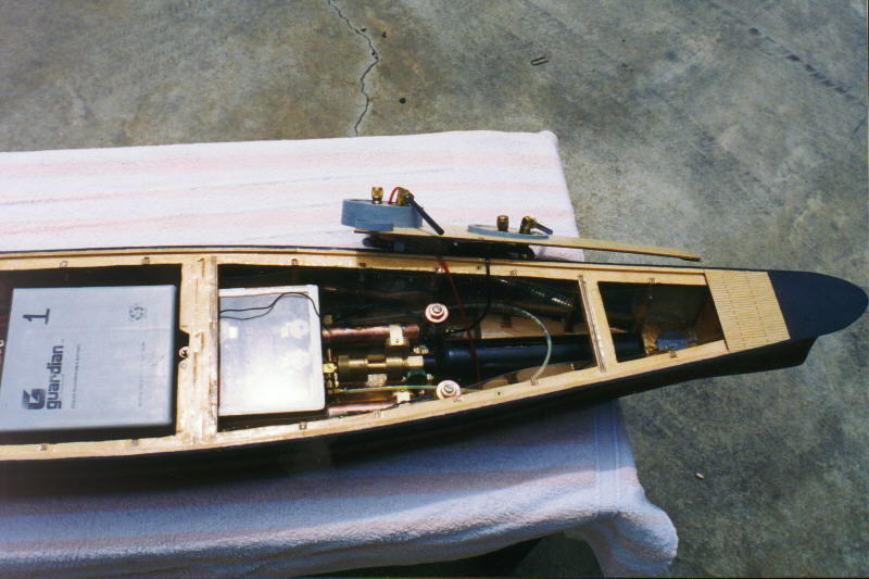
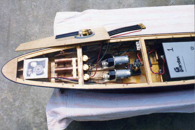
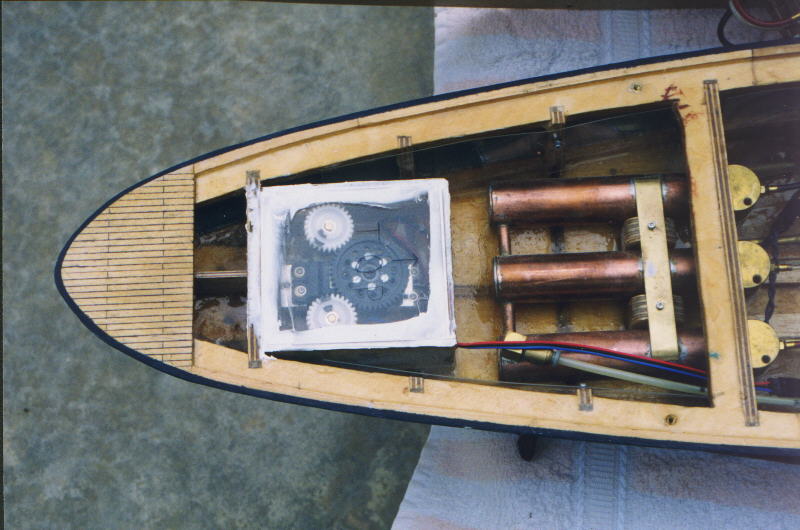
This picture shows an overall bow view of the USS North Carolina. In addition to showing off a bit of the deck planking (done with Paper Mate pen and ruler), it shows some of the systems and how they fit together. At the extreme bow is a small lead weight which I added because the bow seemed to ride just a little high. Next is the 9 oz. CO2 bottle, with lite Swampy regulator. Surrounding the regulator are the bow expansion tanks, above which we can see the two sidemounts. To the left of the tanks, we can see the watertight radio box which is a rather snug fit. Last, on the left is the massive battery. I generally tend to favor this sort of layout of the ship beacause it results in a layout that's relatively sane and repeatable, plus things tend to fit.
 The CO2 System
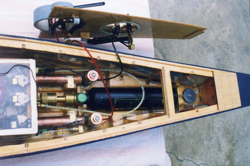
Here we can see the overall bow CO2 system of the ship. The 9 oz. CO2 bottle is manufactured by Tippman, while the regulator is a Swampy Lite regulator. This is connected to the bow expansion tanks with 5/32" hose, and a pair of Parker fittings, one straight fitting, and one swivel fitting. I like the Parker quick connect fittings and the 5/32 hose because they are much more reliable and less prone to breakage and leaking than the flimsier hoses. The quick connects are also more convenient to use. They're also more expensive, but...
 Bow Expansion Tank
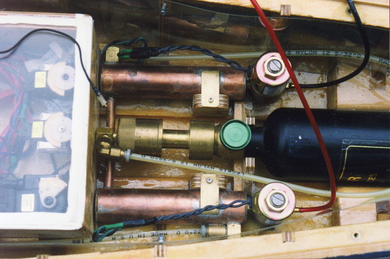
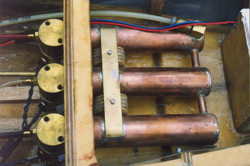
This view shows the bow expansion tank and solenoids. Expansion tanks are used to provide a ready reservoir of pressurized gas so that when the guns are fired, there is an immediate burst of gas, and no need to wait for gas to flow through the regulator and make its way through narrow CO2 lines to the valve. This is an added bonus with the solenoid valves, which allow more flow than poppet valves. The end result is a bigger bang.
So... The USS North Carolina contains the largest expansion tanks I've ever put in a ship. They are 3/4" x 4" long, and are cross connected by 1/4" copper tubing. To follow the gas flow, it comes in through a quick connect fitting and high pressure hose in the top, and then flows through the 1/4" copper connector to the lower tank, and through another high pressure fitting to the stern tanks, which are covered in another picture.
Also, the solenoids are the popular KIP variety that we're all familiar with. They are attached to 1/8" hose barbs which have been shortened and soldered into the ends of the tanks. I align the hose barbs carefully so that when the valves are tightened down on the 3/16" Du-Bro plastic washers I use for gaskets, they align correctly. It's perhaps a bit difficult, but I think it's worth it.
 Sidemounts on Deck!
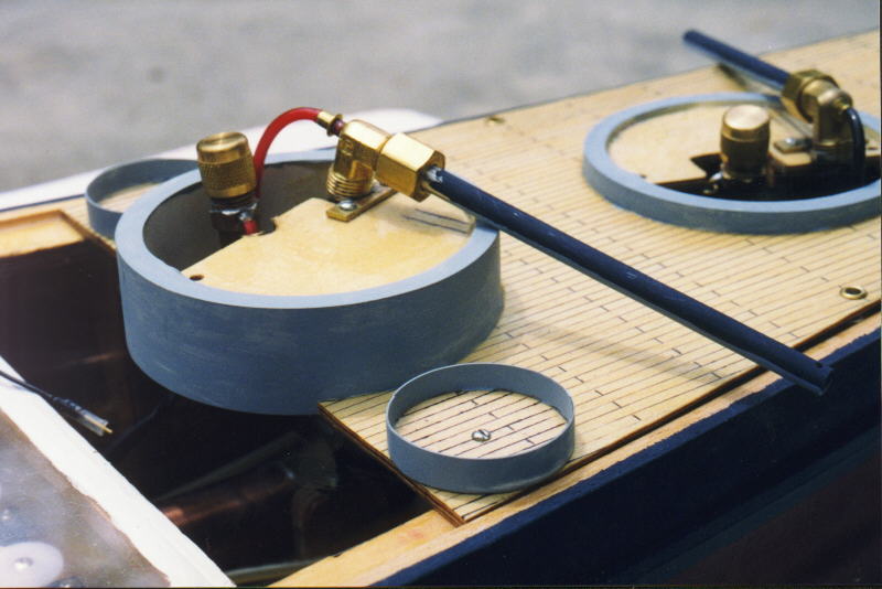
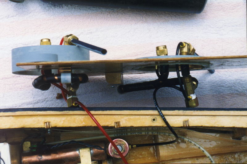
This photo shows the two sidemounts as they appear when the deck is placed on the ship. Each sidemount has a 4.5" (scale length) stainless steel barrel, which connects to the traditional "Foster Breech". Okay, the slightly modified "Foster Breech"... The bypass to the back of the breech is a relatively recent (1995) improvement. I originally soldered the breeches to brass plates which were screwed to the deck. However, this did not prove durable enough, so they have since been replaced with aluminum clamps which directly attach to the barrel, and are much more durable. I took special care to run the magazines so that the fill caps came up next to the breech for easy loading and tweaking. Both sidemounts are aimed slightly forward for pursuit purposes, and have fairly generous down angle. I later raised the starboard sidemount, however, because it was aimed too low and was therefore rather difficult to aim. One of the key things with bow sidemounts is that they need to have a rather shallow angle so that they have a larger area of effectiveness. If they have too much down angle, they are nearly impossible to aim, because the bow of the ship doesn't move side to side nearly as easily as the stern.
 Sidemounts Below Deck
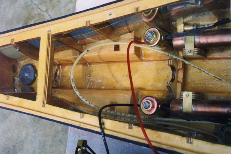
Below deck, we can see the guts of the two sidemounts. The guns of the North Carolina are a relatively new modification of the traditional Foster design. The primary difference is that the bypasses to the breech and magazine are ported from further up on the tee fitting, rather than the cap so that the piston has to rise a certain amount before the bypasses activate. This provides much more reliable single shot action. The magazines and upfeed tube are protected with Radio Shack 1/4" spiral cable wrap, so that they won't be damaged by any stray bb's which get past the internal armor. The magazines are attached to the bottom of the deck securely with cable clamps and screws. Also note that the hoses are color coded. I like to do that to prevent possible confusion (Red = Right), and because I can...
 Bow Channeling
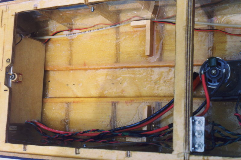
There are three basic defensive systems in any ship. The first and most obvious is the pump. The second and rather obscure, because it's not mentioned in the rules is the internal armor, which can be seen here bolted to the ribs. I have often used 2 liter soda bottle plastic, but in the North Carolina, I decided to break out the .030 Lexan instead. It's worked very nicely. Finally, and perhaps least well understood is water channeling. Water channeling exists to help prevent water from pooling in inconvenient areas of your ship, and to help channel it directly to the pump. In the North Carolina's case, the water channel is a 1/4" deep channel down the center of the ship, with various additions at the bow and stern to help prevent water from pooling there. In the bow, there is a block, which can be seen under the lead weight which helps fill that area, while there are also shaped blocks which go on either side of the CO2 bottle to prevent water from pooling there either. The idea is that rather than allowing the water to collect in the bow, it is forced to the stern, where the pump can deal with it.
 Radio Box
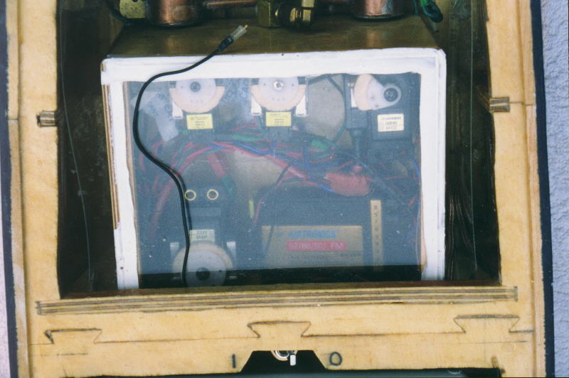
This picture shows a top view of the radio box. The radio box in the USS North Carolina is constructed of 1/8" aircraft plywood, with a 1/4" square "lip" on the inside for the 1/8" plexiglass lid to sit on. The seal is achieved by running a bead of silicone around the top of the lid so that it covers the lid and box edges. This way, the lid can be removed simply by cutting the glue bead with an X-acto knife. At the bottom of the picture, visible through a slot in the cross brace, is the main power switch. This switch is wired so that it turns the radio and motor power on and off. The solenoids and pump are wired separately. At the lower right of the box is my Airtronics 6 channel receiver, which is on HAM radio frequcncy 50.100. I got my HAM license this year specifically so that I could use one of these frequencies, as they are less crowded than the other frequencies.
To the left of the receiver is the throttle servo, which is the well known microswitch variety. Across the top of the box, you can see the two gun servos, which are Tower System 1000 micro servos. I used them because they have a much faster transit time than the normal standard servos, and I prefer speed when I'm dealing with the guns. Their small size also makes them easier to deal with. The other servo is the pump servo, which is another standard servo, and has a 11A micro switch attached to it rather than the cheapie 5A switches, because the pump draws a lot more power than the other systems in the ship. Note also the bags of dessicant shoved between the servos. Dessicant helps prevent moisture in the box (humidity) from condensing on the radio gear and causing interference problems.
The wiring in the box is the normal octopus which I have been using for the last several years. Essentially, the main bus wires come in and I simply attach leads to them for the various other subsystems. The entire thing is assembled outside the box, then inserted, tested, and glued in place. The servos (except for the pump) are also equipped with plugs so that they and their switches can be removed from the box if maintenance should be necessary. Finally, the red blob in the right center of the picture is my receiver protection circuit which consists of a capacitor and a couple of diodes, which are there to protect the receiver from reverse voltages and voltage spikes.
 Radio Box Part 2
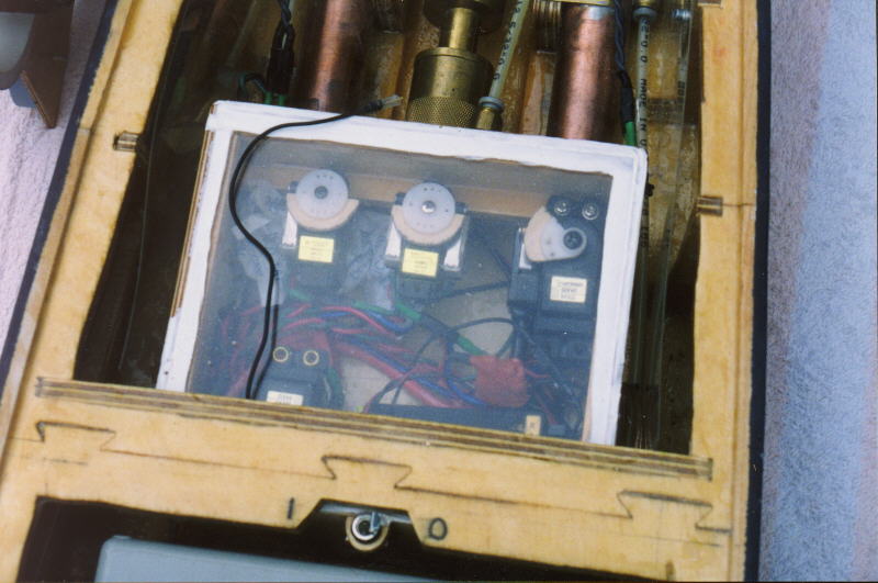
This view shows a bit better the servos in the front of the box, as well as the rail they are attached to. Each servo is attached with screws so that it can't flop around and get into trouble. Otherwise, I can't really think of anything else here that I haven't covered above...
 Midhips Channeling
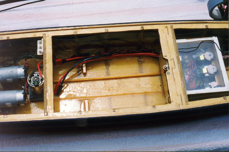
This view shows the amidships water channeling in the North Carolina, as well as some other interesting stuff. The channeling is (of course) simply an extension of the 1/4" deep channel which was begun in the bow. The internal armor also continues through this view, and here we can see a closer view of the ship's wiring. At the top is the rudder servo cable, as well as the 5/32" hose which connects the bow and stern expansion tanks. At the bottom can be seen the main wiring which I keep on the other side from the radio wires in an attempt to reduce potential intereference.
A note on the watertight box - note that the wires are each individually super glued into individual holes in the box, even for the power switch at the top of the box. Drilling holes and gluing each wire individually helps to prevent leaks, which is very, very important. I'd much rather have a watertight box than a water resistant box... Drying out radio equipment at lakeside is not fun!
 Main Wiring
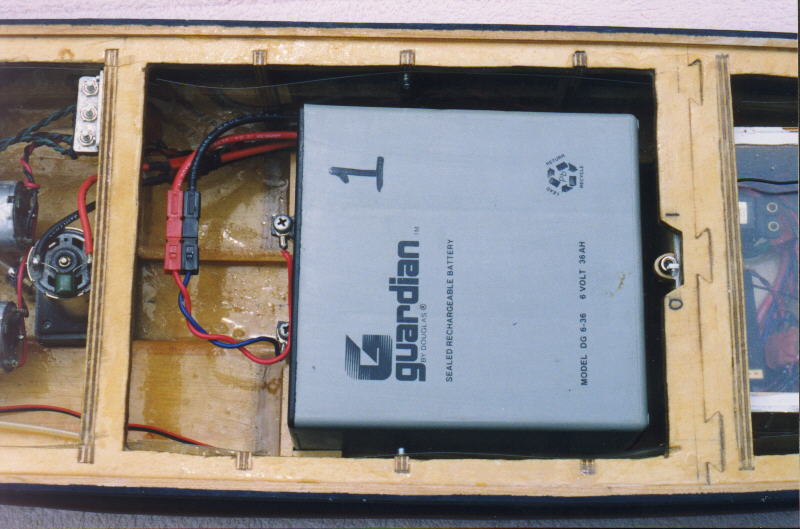
Here we can se a closer view of the main wiring of the ship. The large cables are Deans 12 gauge Ultra Wire. This stuff has 1660 very fine strands, and is the best wire I've ever seen. I used it for my "main bus" which goes from the battery, into the box, and to the pump, since the pump is the major high current item. The smaller paired black and red wires are 18 gauge, and go to the motors, while the braided red/green/black set are 20 gauge, and go to the stern gun test switches which are visible alongside the pump and motors. Stuff like the lights us thinner 24 gauge wire. Also visible are the battery braces, which keep the battery from moving around too much. The battery connector is the popular "Dynamite/Sermos/LiteSpeed" connector which is available through Tower Hobbies. They are interlocking, modular, polarized connectors which have self cleaning silver contacts.
 The Power Source
Here we can see a close up view of the power source of the USS North Carolina, a Guardian 6V 36AH battery. I highly recommend this type of battery for the larger battleships, like the North Carolina, South Dakota, etc., because of its great amount of power, and its convenient size. Six volts is a convenient voltage to use because of the availability of surplus motors and other stuff that works good on 6V. The 36AH comes in very handy because it essentially means that in the normal fleet battle, I have no need to worry about running out of energy. In fact, at the end of the second sortie, the extra power gives me an advantage over those ships which are beginning to run low on power. In case you wonder, the wires directly connected to the battery are some other 14 gauge stuff which the Tennessee was wired with, and since this was one of the Tennessee's batteries... The North Carolina's new batteries have Ultra Wire soldered to their contacts.
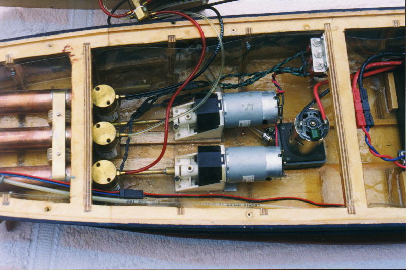
 Stern View
This picture provides an overall view of the stern of the USS North Carolina. At the far right, we can see the battery, where we just left off. Next are the stern gun test switches, and the pump and outlet. Just to the left of those are the drive motors and gearboxes, then the stern gun solenoids and expansion tanks. Just above these, we can see the stern guns, attached to the stern deck. Finally, at the farthest left is the rudder box, with the geared rudder system inside it. These subsystems will be discussed shortly. Also notable, since I don't have a picture for it, is the stern ending of the water channel. Behind the gearboxes, the very stern of the ship is filled with solid balsa, so that water absolutely cannot collect there and sink the ship.
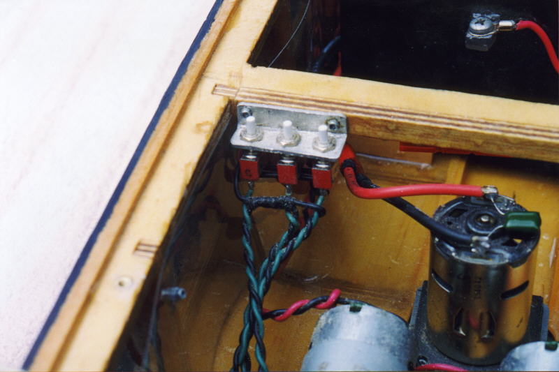 Test Switches
Here, we can see the triple stern gun test switches. One of the very nice things about solenoids is that they can be electrically controlled and with the appropriate circuitry, testing and tweaking is much easier than for a similar pneumatic system. This circuit consists of three SPDT (single pole/double throw) switches, which are mounted to a bracket(obviously), and wired as follows: the common wire is connected individually to each solenoid; the normally closed connection is connected to the switched lead from the radio box so that when the servo presses the switch, all three guns fire; the normally open connection on the switch is connected to battery positive, so that when the test switch is pressed, that individual gun fires. The negative lead bypasses the switches and simply runs common to all three solenoids. I connect Deans plugs to the switch assembly so that it can be easily removed from the ship for maintenance. I've also placed a circuit similar to my radio protection circuit on the switches so that reverse voltage spikes caused by the solenoids will be absorbed and won't cause trouble in the rest of the system.
 Pump and Outlet
Here we can see the pump and pump outlet. The pump is built to a design I have been using essentially since 1992, and have been very happy with. This particular pump was built in 1996 for my previous USS North Carolina, and has provided sterling service since. Since it's made of Lexan, it should provide excellent service for many years in the future, too! The pump motor is the popular Tamiya RS-540 motor, to which I have soldered a .047 uF capacitor and the 12 gauge Ultra Wire. It is connected to the wiring bus with a Deans Ultra Plug, which I am beginning to like more and more for its convenience and excellent construction. I generally tend to use different plugs for each connection, however, just to ensure that it's impossible to connect the wrong things together, or get them backward.
The pump outlet is a Greg Wilson design which I have copied and used since 1992 with good results. It's a 5/32" tubing (for the 1/8" bore), which is soldered to a plate, so that it sticks through about 1/16", and the plate is soldered to a 9/32" tubing. This design is supposed to reduce turbulence and promote a better flow. It seems to work nicely, and I like the convenience and the fact that it doesn't look horribly ugly where it exits the ship. It is connected to the pump with 1/4" vinyl hose and a pair of hose clamps. The hose clamps are absolutely necessary, because on hot days, the hose gets soft enough that the pressure from the pump will blow it off the pump, or outlet, with the result that you sink. Not very fun, that... The pump outlet is mounted at an angle, mostly for convenience, and so that the water doesn't have to change direction too much as it flows. Changing the water's direction reduces the pump's flow, much like taking a sharp turn in your car reduces it's speed. As a result, since I want the maximum pump flow possible, I try to keep the flow to the outlet smooth.
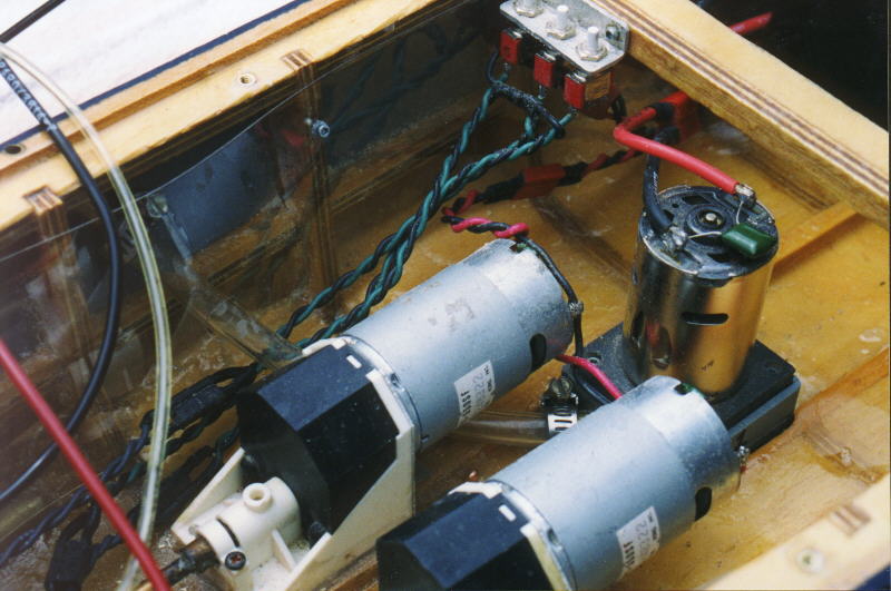
 Drive System
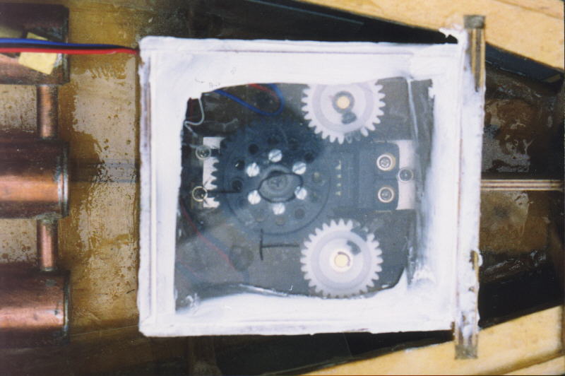
The drive system for the USS North Carolina is the tried and true Traxx Gearbox system. The drive motors are a pair of surplus specials which are similar to the famous Johnson HC600 series which are available from Swampy and others. They are connected to the wiring system with a Deans 4 pin power plug, and have .047 uF capacitors soldered to them to reduce radio interference. The gearboxes are the standard Traxxas variety, which are slightly modified by the addition of an aluminum plate at the back, and another aluminum plate on the inside. These are added to stiffen the gearbox and provide a heat sink so that if the motors overheat, they won't melt the gearbox. The motor shafts are 1/8" solid brass rod, while the stuffing boxes are the standard built up brass tubing variety.
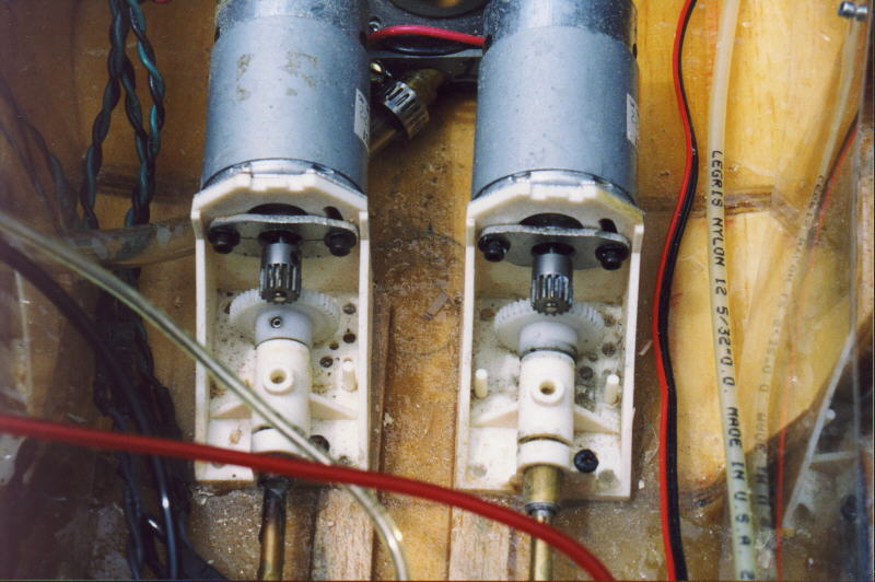 Inside the Gearboxes
This picture shows a close up view inside the gearboxes. Instead of the usual Traxxas 32 pitch nylon gear and 32 pitch pinions, I special ordered from Stock Drive Products some 48 pitch nylon spur gears and used standard 48 pitch racing pinions. This gives me a smoother drive system, as well as more speed adjustability The downside is that the smaller teeth are less durable, so I'd better not run through too many rocks... Also notable is the inside aluminum stiffener, behind the pinion gears. The two gearboxes are simply siliconed to the bottom of the hull, where I had to add some wood inside the water channel to provide a greater "pad" surface for the gearboxes to be glued to. I siliconed the gearboxes down instead of using screws, because the silicone is strong enough, and also because it absorbs vibration and cuts down on gearbox noise. Also, that way, I don't have any pesky screws in the bottom of my hull where water can get in and rot the carefully sealed wood.
 Stern Closeup
This picture shows a close up view of the stern expansion tanks, and the rudder box, which we will be viewing shortly.
 Stern Expansion Tanks
The stern expansion tanks are very similar to the bow expansion tanks, except that there are three of them, connected by short pieces of 1/4" copper tubing. Each solenoid has a separate, large (3/4" x 4") tank, so that when they are all fired simultaneously, each has a large reservoir of pressure available on demand, so that it can fire quickly and won't rob the others of pressure. The gas inlet and cross connections are at the other end from the valves to help enhance this effect. In order for the gas to get from one tank to the other, it would have a greater distance to travel than simply to go out its own solenoid. At least that's the theory. It works nicely, though...
 Stern Guns on Deck!
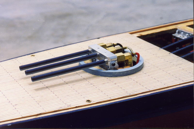
This picture shows the stern guns as they are mounted on deck. The 5" long stainless steel barrels are mounted to an aluminum mount which was specially machined according to some plans I provided. This mount provides for a slightly raised center barrel, as well as a slight inward angle on the outer two barrels, for a roughly triangular shaped shot pattern. This mount is bolted to an aluminum bracket, which is bolted to the barbette. Behind the mount, the breeches are identical to those on the sidemounts. Since this picture was taken, I have put barrel protectors over the stern gun barrels to prevent bb's from damaging them. Nothing ruins good barrels (and good aim) faster than a bb dent.
 Stern Guns Below Deck
This view shows the guts of the stern guns, which are essentially identical to the sidemounts. Again, the hoses are color coded, and since trying to make spirals of all those magazines would be a pain, they simply run straight forward, into the bottom of the superstructure. The magazines are also protected with 1/4" spiral wrap, and are attached to the deck with a simple block of plywood, zip ties, and a couple of screws. Since they aren't subject to ramming, they don't have to be quite as secure as the sidemounts.
 Rudder Box
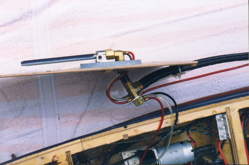
This rudder box is the first one I have ever built, and I'm very pleased with it. Previously, I depended on waterproof servos, but for this ship, I decided to go all the way and build a water tight rudder box. Inside the box is a standard Airtronics servo, with a 44 tooth spur gear on it. This drives a pair of Traxxas gears which are directly attached to the 5/32" rudder posts. The geared rudders provide for precise control and much more accurate rudder movement than pushrods. They also allow greater rudder travel, sometimes too much. I originally tried a 48 tooth gear, and decided that was too much throw. Luckily, I made the aluminum servo mounts so that they were adjustable, and I was able to fit the 44 tooth in nicely. The rudder posts contain an integral o-ring seal, much like a gun breech, so that water cannot enter the box through the rudder posts. The box is attached to a rib at one end, which has had its center filled with plywood, and is otherwise similar in construction to my radio box, made of 1/8" plywood with a 1/4" square lip and a 1/8" lid. The rib was notched on the outside of the box so that water can flow from behind the box forward to the pump. Overall, I'm quite happy with this system, and I would highly recommend it.
 The Stern
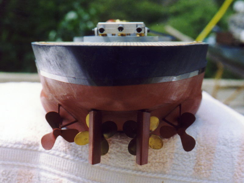
This picture shows a stern on view of the USS North Carolina, which makes the stern gun pattern rather obvious, as well as showing a good view of the props, rudders, and drag props. The drag props are 1.75" Dumas bronze props, which are mounted to solid 3/16" brass drag shafts, which are very securely mounted to the hull. They're heavy, but they look good and provide plenty of drag. And they should never break... The main props are 1.75" Exact Miniatures, which I suspect are no longer available, but Swampy is making something similar now. For a ship this size, I like to use 1.75" props because their size and additional blade area should provide better acceleration. The rudders are made from 1/2" thick laminated plywood sanded to a teardrop shape and are located directly behind the props so that they can most efficiently utilize the prop wash.
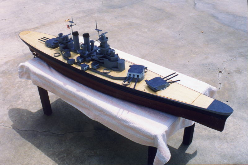
 Port View...
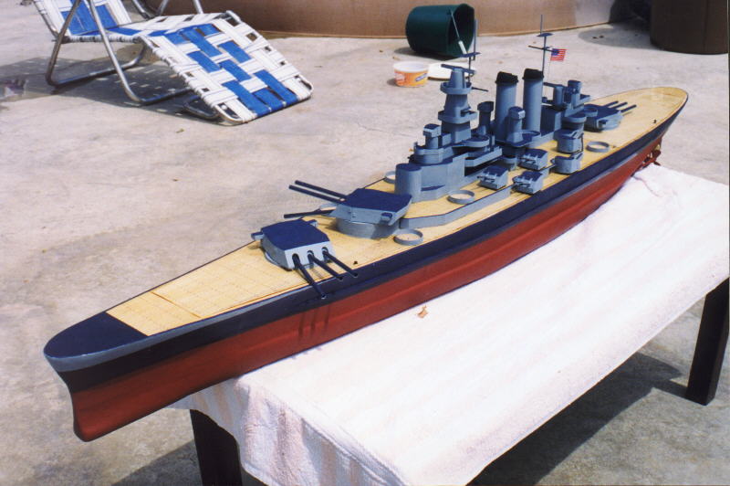
 Starboard View...
Finally, to close off the page, I have a couple of "cheesecake" shots showing the port and starboard sides of the USS North Carolina to good advantage. What a beautiful ship, eh???
That's all for now, folks - hope you've enjoyed the tour!