Welcome aboard the DKM Bismarck! Today, we will be looking at a number of the ships systems, as well as how they all fit together to make the PRIDE OF A NATION, A BEAST MADE OF STEEL, ahem ... one of the hobby's most formidable battleships. So, without any further ado, let's begin our tour!
But ... before we get started, here's a brief video of the Bismarck running sea trials Sunday at Nats 2021. Looking good!
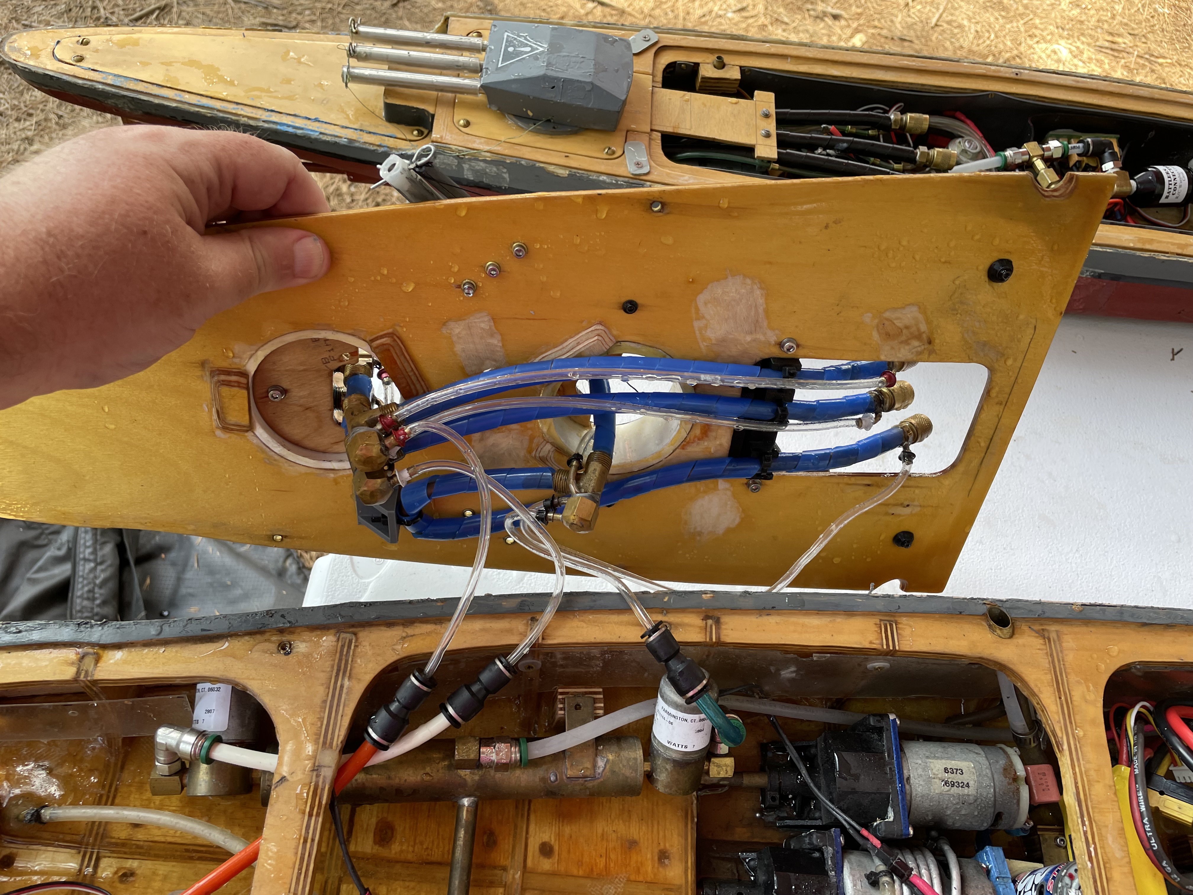
 The CO2 System
Here we can see the overall bow CO2 system of the ship. The 12 oz. CO2 bottle is a standard paintball bottle with a "Smart Parts" 90 degree on/off valve, while the regulator is a Strike Models regulator (the good version). This is connected to the bow expansion tanks with 1/4" nylon hose, and a pair of Parker swivel fittings. I like the Parker quick connect fittings and the nylon hose because they are much more reliable and less prone to breakage and leaking than the flimsier hoses. The quick connects are also more convenient to use. They're also more expensive, but... As a wise man once said, "The bitterness of poor quality is remembered long after the sweetness of low price has faded from memory."
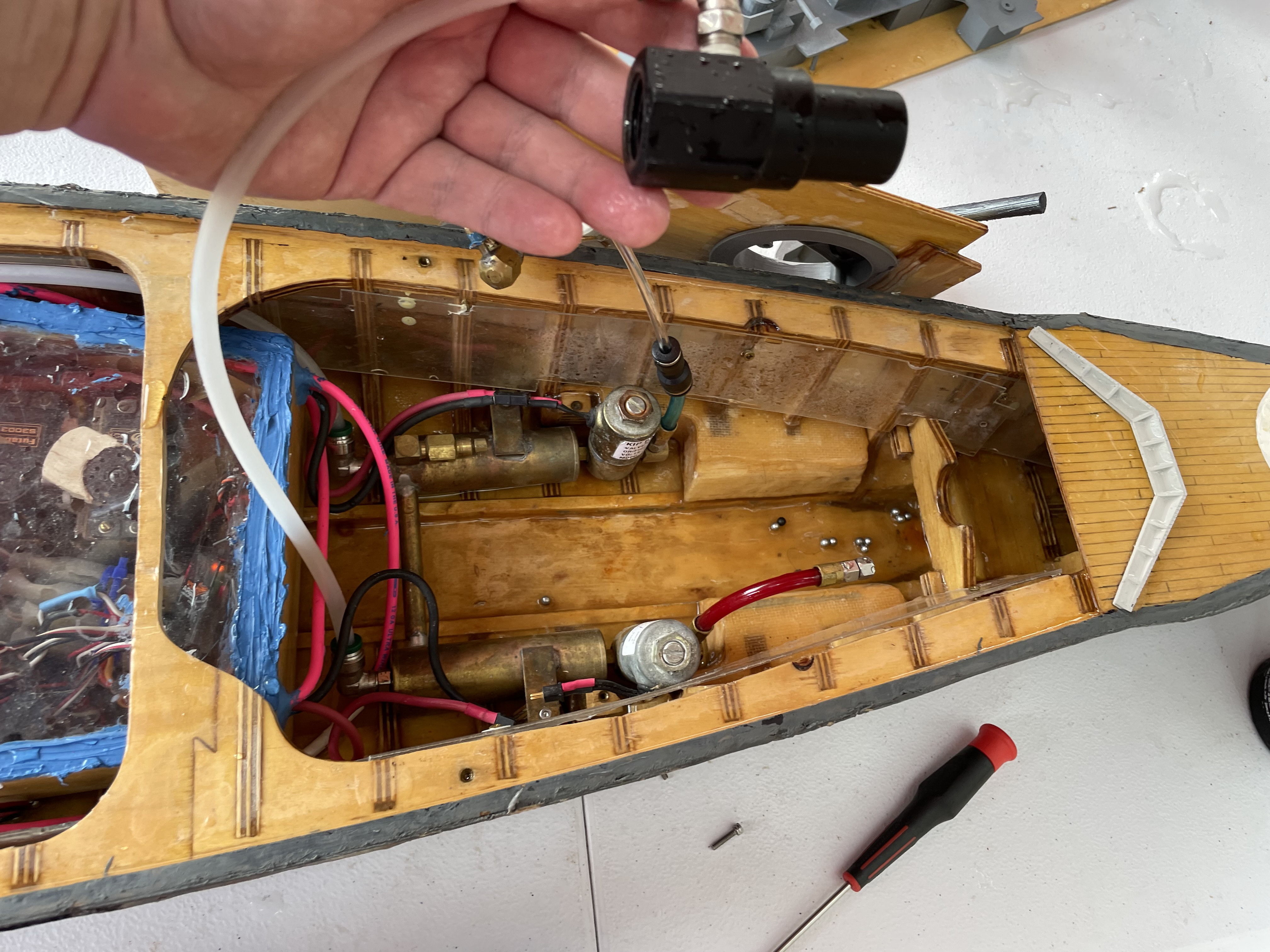 Bow Solenoids and Regulator
This picture shows a better view of the regulator, the bow expansion tanks and solenoids. Expansion tanks are probably not as important now as they used to be, but I still like them; they give me a warm fuzzy when the guns go bang.
The expansion tanks in the Bismarck are actually a Clippard product, which saves on soldering. The gas flows from the regulator, through the nylon hose into the quick connect fitting and high pressure hose on the bottom tank, and then flows through the 1/4" copper connector to the upper tank, and through another high pressure hose/fitting to the stern tanks, which are covered in another picture.
The solenoids are the popular KIP variety that we're all familiar with. They are attached to the tanks via Clippard 10-32 unions. I think. I should look more closely sometime. I'm afraid to look more closely sometime.
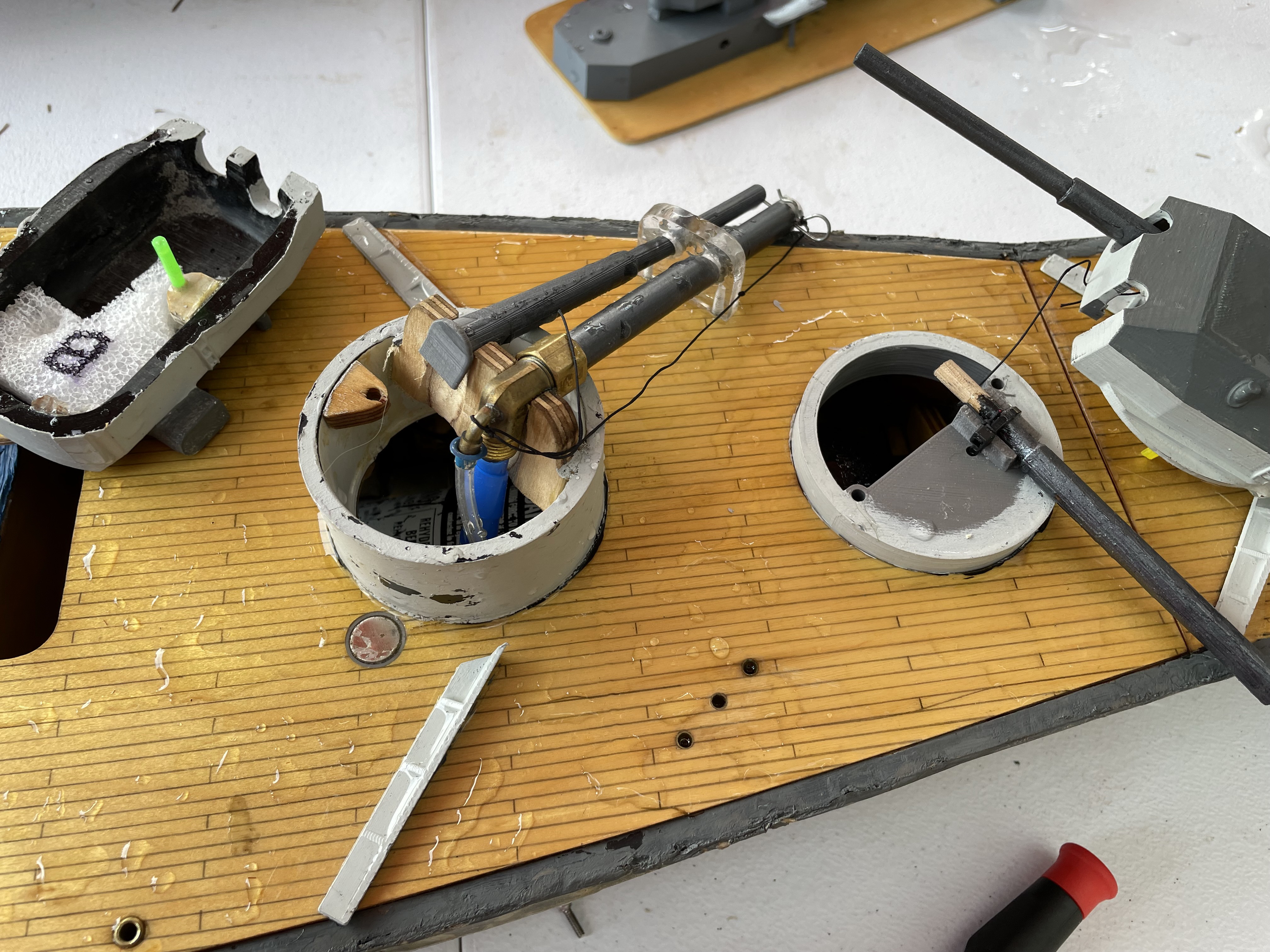 Bow Sidemounts
This photo shows the bow sidemounts as they appear when the deck is placed on the ship. I ran short on time prior to the 2021 Nats, and didn't really expect to run a single pump/5.5 gun unit system anyway, so I just put an old "fake" barrel in the starboard sidemount barbette. The port (working) sidemount is mounted in the old plywood/lexan mount from back when she was able to have double sidemounts. The fake barrel is 3D printed ABS. I think it looks kind of spiffy. The sidemount has a 5" stainless steel barrel, which connects to a modified "Foster Breech". Both this, and the stern sidemount have lots of down angle, and are set up so that they will impact as close to the ship as possible for those devastating below the waterline hits.
Bow Sidemount MagazineReusing an earlier picture (ahem), below deck, we can see the magazine for the bow sidemount. I prefer to keep my magazines as straight as possible to avoid jams, but sometimes a little curve is necessary to get things to fit. In this case, the magazine was hand bent to the desired shape, and while it appears loose, once the deck is in place, the hull cross brace holds it in position quite firmly. This might also be because I ran short on time... The magazine is protected by some 1/4" spiral cable wrap. Anyway, one other thing you might note is that the solenoids have 1/4 Clippard hose attached to them, while the gun has a smaller hose. The hoses are a relic of her 2016 dual sidemount configuration. Personally, I think that's more than a bit excessive ("Nothing exceeds like excess!"), but yeah. So, rather than replace everything, I just got some quick connect adaptors from Amazon to adapt the two different hose sizes, and provide for convenient lakeside servicing.
 Radio Box
This picture shows a top view of the radio box. The radio box in the Bismarck is constructed of 1/8" aircraft plywood, with a 1/4" square "lip" on the inside for the 1/8" plexiglass lid to sit on. The seal is achieved by running a bead of silicone around the top of the lid so that it covers the lid and box edges. This way, the lid can be removed simply by cutting the glue bead with an X-acto knife.
At the bottom right of the radio box is the receiver, a Spektrum 6 channel model. Its little satellite antenna is at the lower left, and hopefully arranged so that it will provide good rf coverage at various angles. Or whatever it's supposed to do. At the top left of the radio box are the two pump servos and switches. These are a bit old school, as there are now some very nice solid state switches available, but these work, and as long at that remains the case, I'm not inclined to change them. At the lower left-ish are the four electronic gun switches, again slightly old school, but they've been working since 2006.
The buttons on the back of the box are the test switches for the various cannons. Needless to say, not all are in active use. The (ahem) pink Sermos connector is the "power switch". As for the wiring in the box, well, I can't quite speak to that. You'll have to ask Tim. (I'm so ashamed!) Suffice to say, it hasn't burst into flames yet.
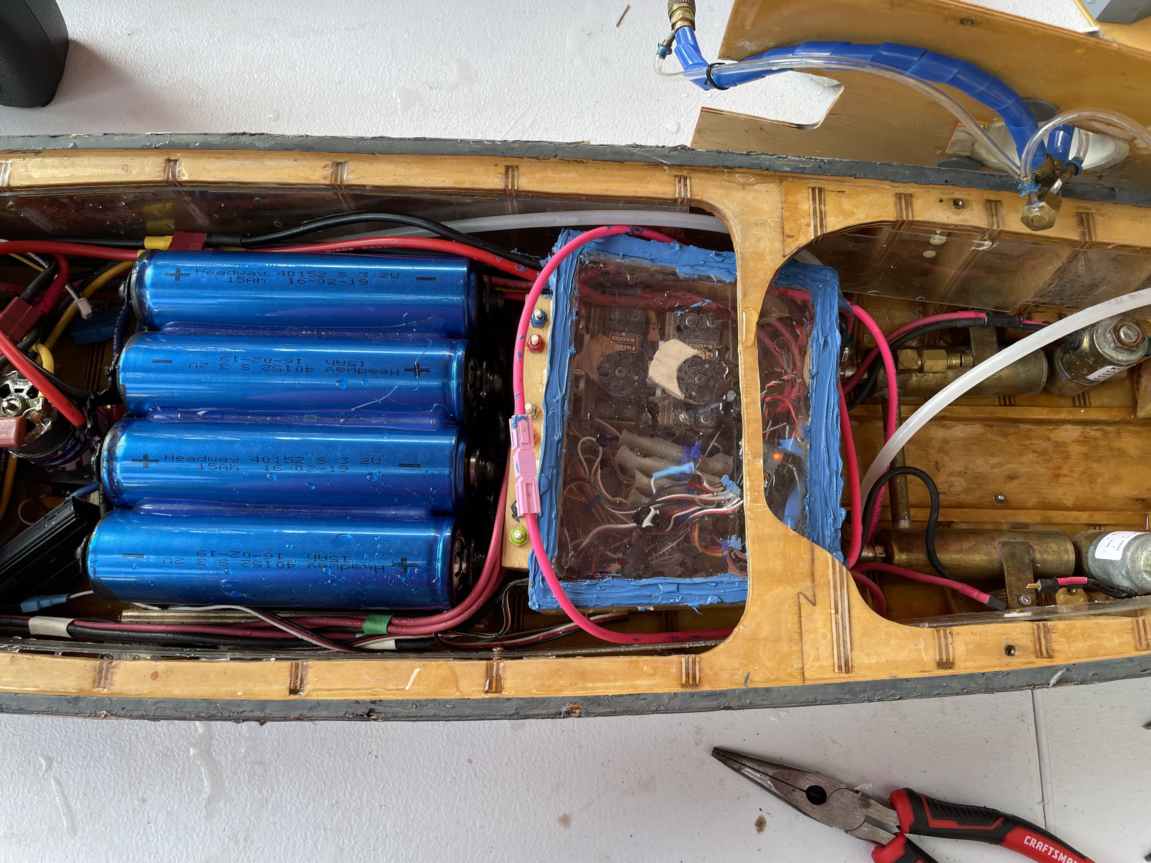
 Batteries (ZOT!)
Here we can see a close up view of the power source of the Bismarck, eight Headway 40152 LiFePO4 batteries. These batteries are wired in a series/parallel combination to provide 6V and 60AH of power. This is extreme overkill, and I've never actually used more than 13AH in a battle. I made my own copper sheet bus bars to connect the batteries, largely because I misplaced the cheap looking ones that they came with. The batteries are connected to the main power via Deans plugs and 10 gauge wire. I know, a lot of people are using higher volate systems nowadays, but the old 6V tech still gets the job done, and doesn't require me to figure out how to find a good 700 size motor replacement.
Also of note in this picture is the 9.9V LifePO4 receiver/solenoid auxiliary battery. This probably isn't necessary, because the 3/32 solenoids generally work well on 6V, but certain parties wanted to make extra sure that the solenoids had plenty of go juice, so here we are.
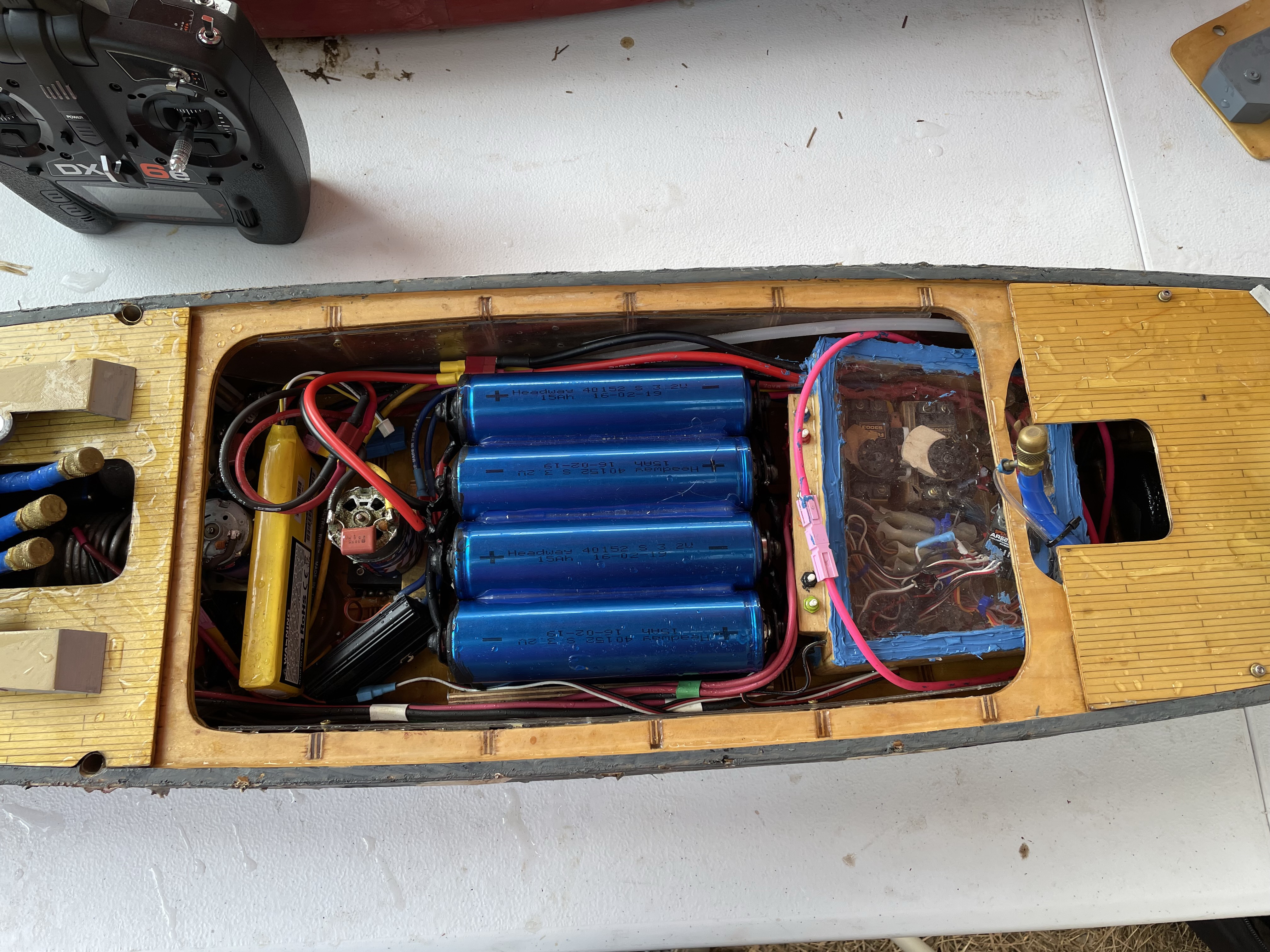
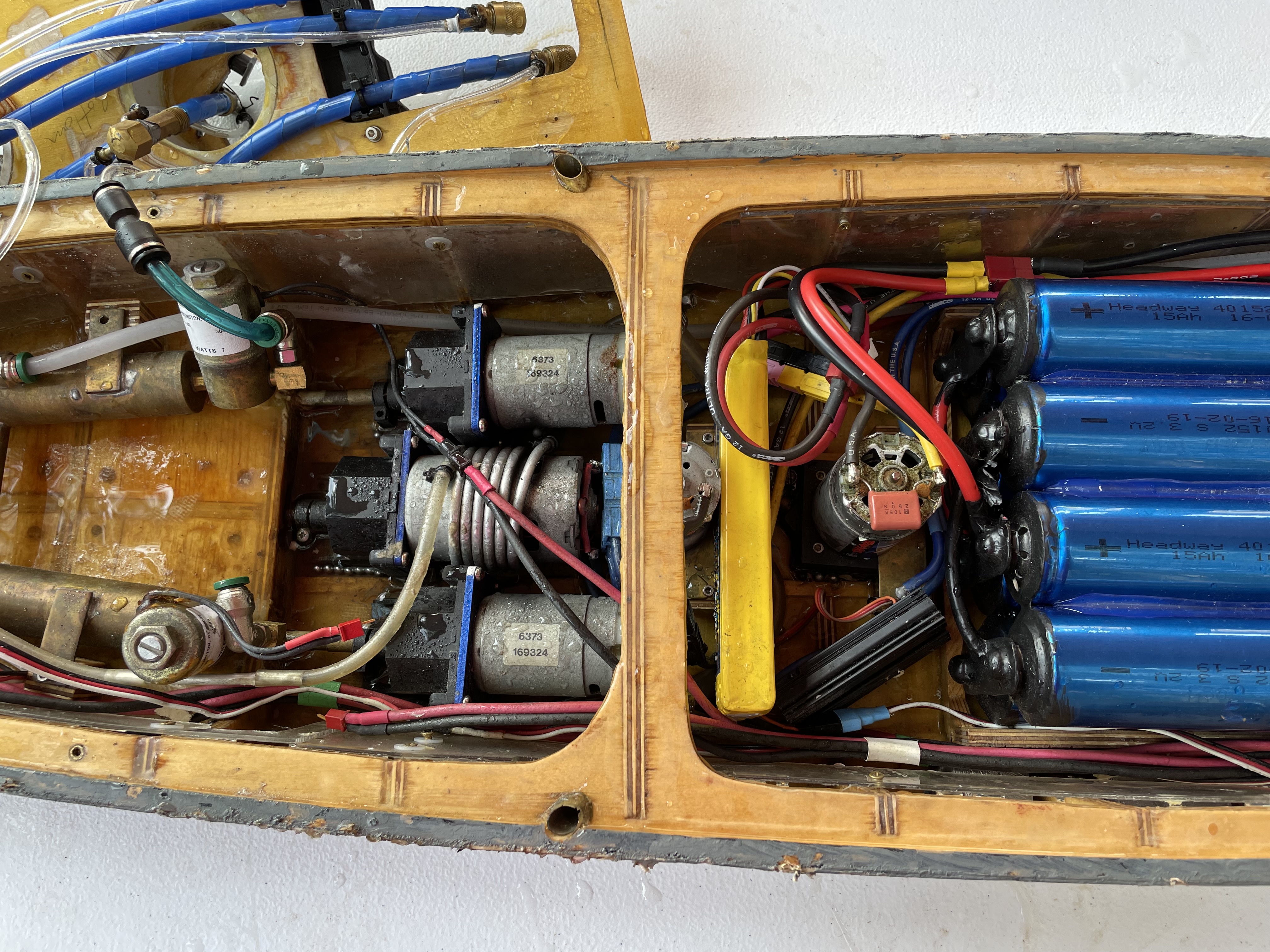 Drive System and Pumps
The drive system for the Bismarck is the tried and true Traxxas Gearbox system. The drive motor is a 700 size surplus special that's been in the ship since 2006. It is connected to the wiring system with a Deans power plug, and has a capacitor soldered to it to reduce radio interference. The gearbox is the newer Traxxas variety, which is modified with a replacement aluminum plate with the correct 700 size motor screw holes/slots. The motor shaft is a 5/32" solid brass rod; for strength, and so that the Traxxas spur gear will be a direct fit.
Yes, there are motors and gearboxes for the wing shafts, from back in the days when reversing systems were a thing (2006). Yes, I'm too lazy to remove them. They're currently very disconnected.
Visible at the bottom of this picture is the 70A ESC that powers the drive motor. This is something rather new for me, as I've generally preferred the microswitch type throttles. I have to say, though, it's been a champ, and it's kind of fun killing time by putting around the lake at "harbor" speeds, while everyone else is frantically rushing to get their boats on the water.
The two pumps are also visible in this picture. They are both powered by Traxxas Titan motors, and are my own design with the classic Foster style impeller and a cast "Alumilite" resin housing that I developed back in 1997 in the garage with Jim Pate. Good times. Good pumps. It's been noted that my pumps aren't necessarily as high peformance as others, but that's a deliberate exchange for reliability. A pump that doesn't prime is no pump at all.
The pump outlets are of the new "laminar" variety. That's probably not the right fluid dynamics word, but it makes me happy. These pump outlets make me happy. No more pump spray in the face, yay!
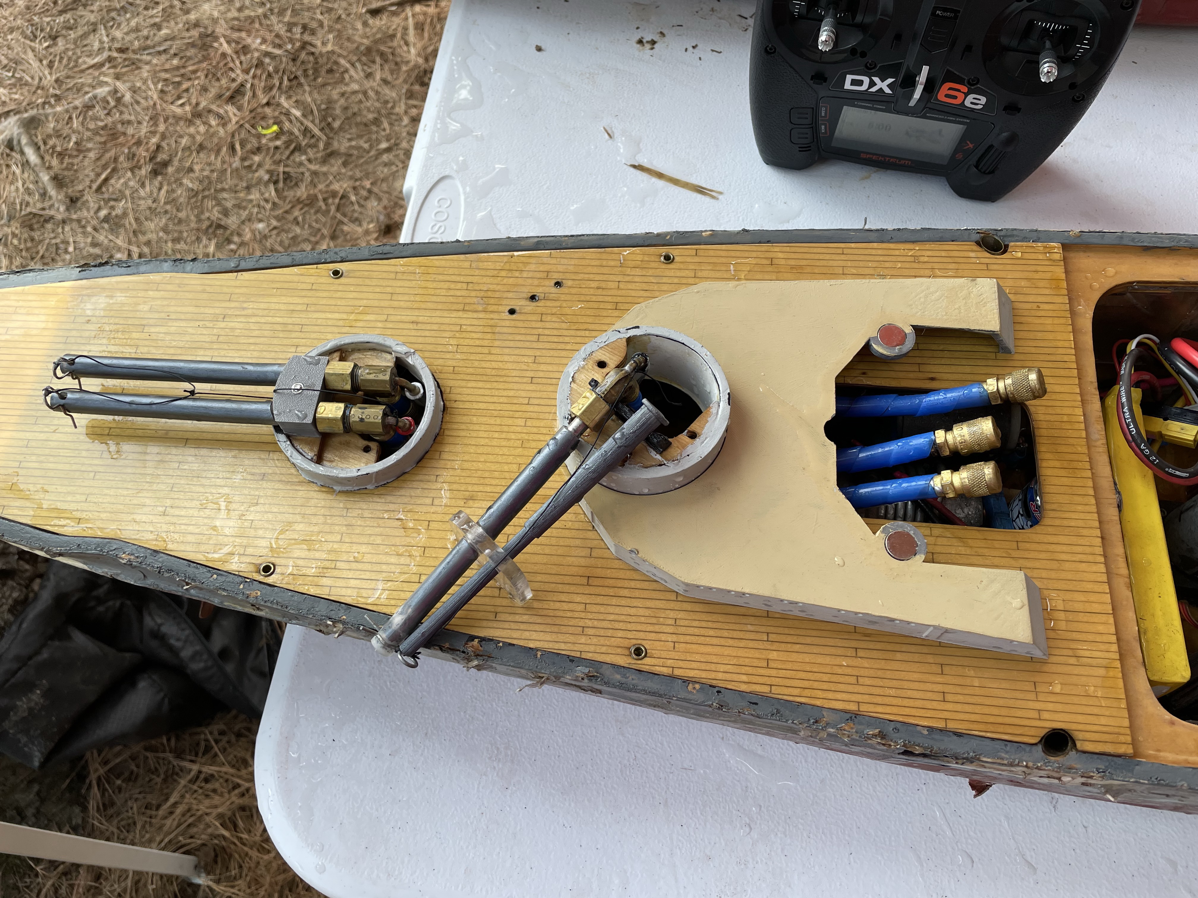 Stern Guns and Sidemount
This picture shows the stern guns and stern sidemount as they are mounted on deck. The 5" long stainless steel barrels are mounted to a 3D printed ABS mount which was designed with a specific convergence and alignment. The stern sidemount, much like the bow sidemount uses the mounting from back when the Bismarck was allowed dual sidemounts. Again, the fake barrel is 3D printed ABS. Oh, and yes, the superstructure is held on by magnets at both ends. Quite spiffy!
 Aft Magazines
This view shows the guts of the stern guns, which should be familiar to you by now if you've looked at my other ships. I ran the stern gun magazines straight forward, because tight curves tend to be the place where bbs get stuck in magazines. Unfortunately, due to the length of the 75 round stern sidemount magazine, I had to put a 180 degree bend in it to make it fit the desired form factor. I have a special tool that helps with making smooth, free flowing bends. I still would prefer a "straight" magazine, though. The magazines are held in place with 3D printed ABS mounts and zip ties. Yes, I've been having too much fun with 3D printing. I should probably have spent more time in the garage instead, right?
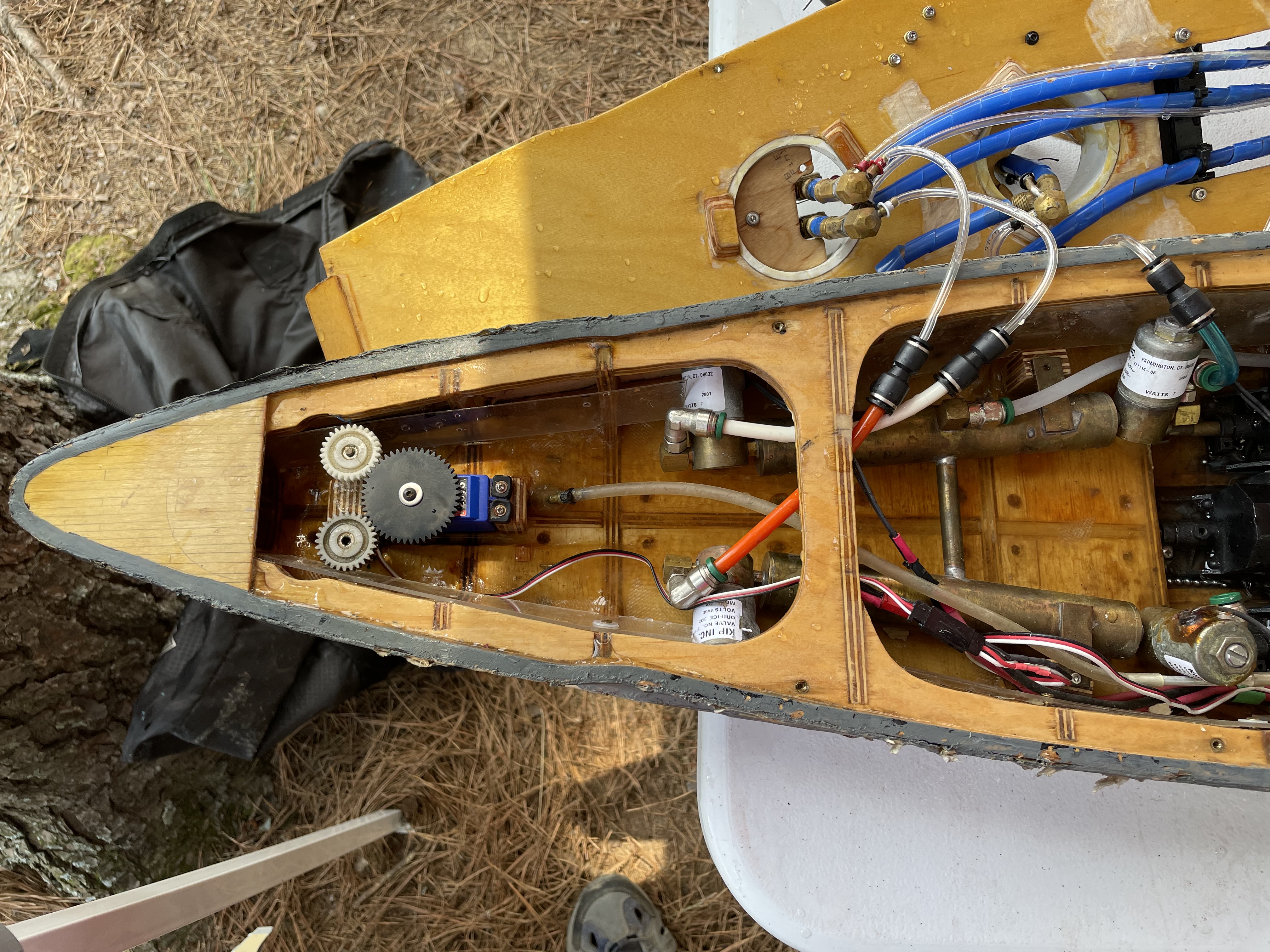 Rudder Gears
Unlike my old USS North Carolina, where I had built an elaborate rudder box, the availability of quality waterproof servos has made an open configuration much more appealing. The Bismarck's rudders are driven by a trusty Traxxas waterproof servo. The servo is topped with a Servo City 44 tooth spur gear; it drives a pair of Traxxas spur gears which are directly attached to the 5/32" rudder posts. The 11:7 gear ratio this arrangement provides gives a very nice amount of throw for the rudders, although that is less important now that computer radios are more common. I did have an issue with it at the 2021 Nats, because the starboard rudder got knocked loose, and would slip a tooth (or three) at the worst possible moments. I need to get that shored up at some point.
Also of note in this picture are the stern expansion tanks, which are much like the ones in the bow, except with more solenoids. You can see the use of the 1/4" to 5/32" quick connect adaptors on the hoses much more clearly here. If you've been keeping count, yes, there are unused solenoids. Again, I'm too lazy to remove them; besides, spares are handy, right?
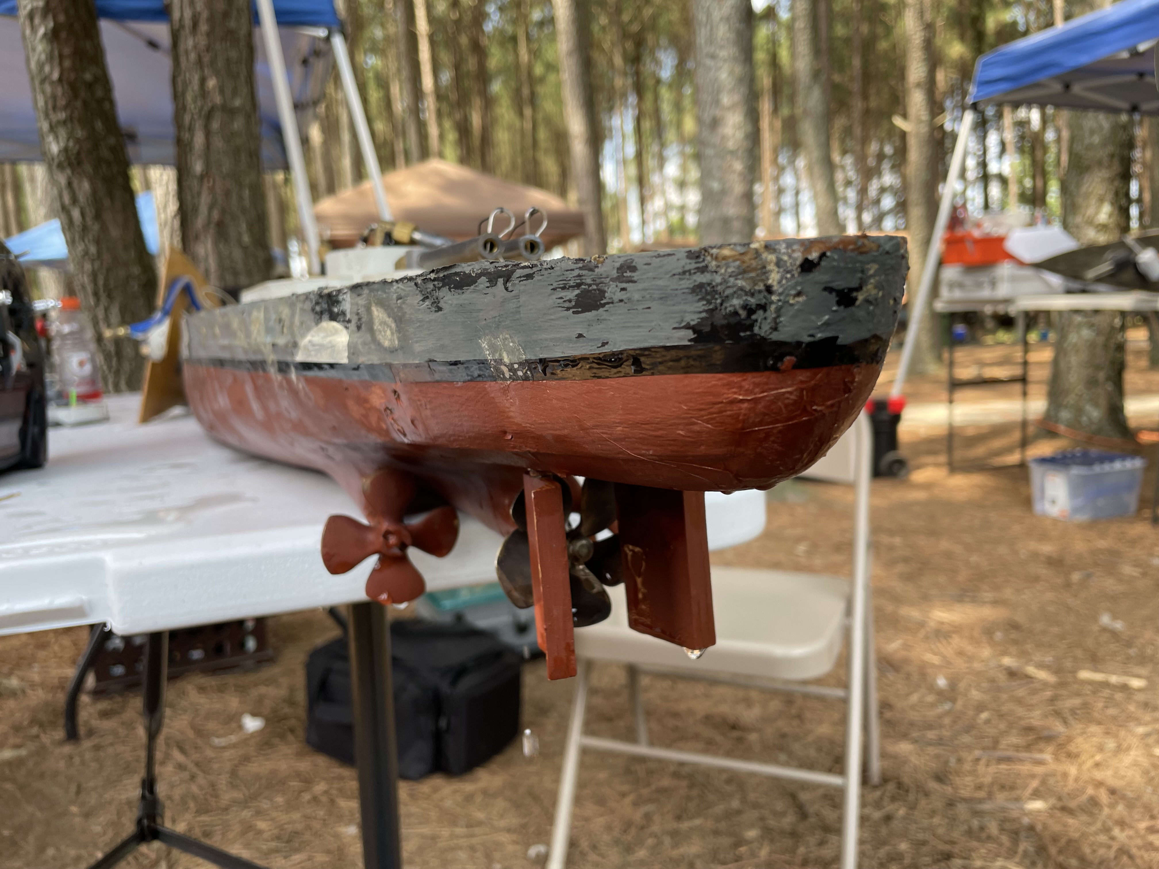 Props and Rudders
This picture shows the stern of the Bismarck, which shows a good view of the props, rudders, and drag props. The drag props are 2" Dumas bronze props, which are mounted to solid 3/16" brass drag shafts, which are nominally operational (but haven't been used since 2006). The main prop is a 2.25" (I think) Prop Shop model (pre-fire). For a ship with a single operating shaft like the Bismarck, having a larger prop helps provide the acceleration it needs. The rudders are laminated plywood, sanded to the currently popular 'fishtail'profile. They are designed to be fairly tall and narrow so that at full deflection, they provide maximum coverage to the prop.
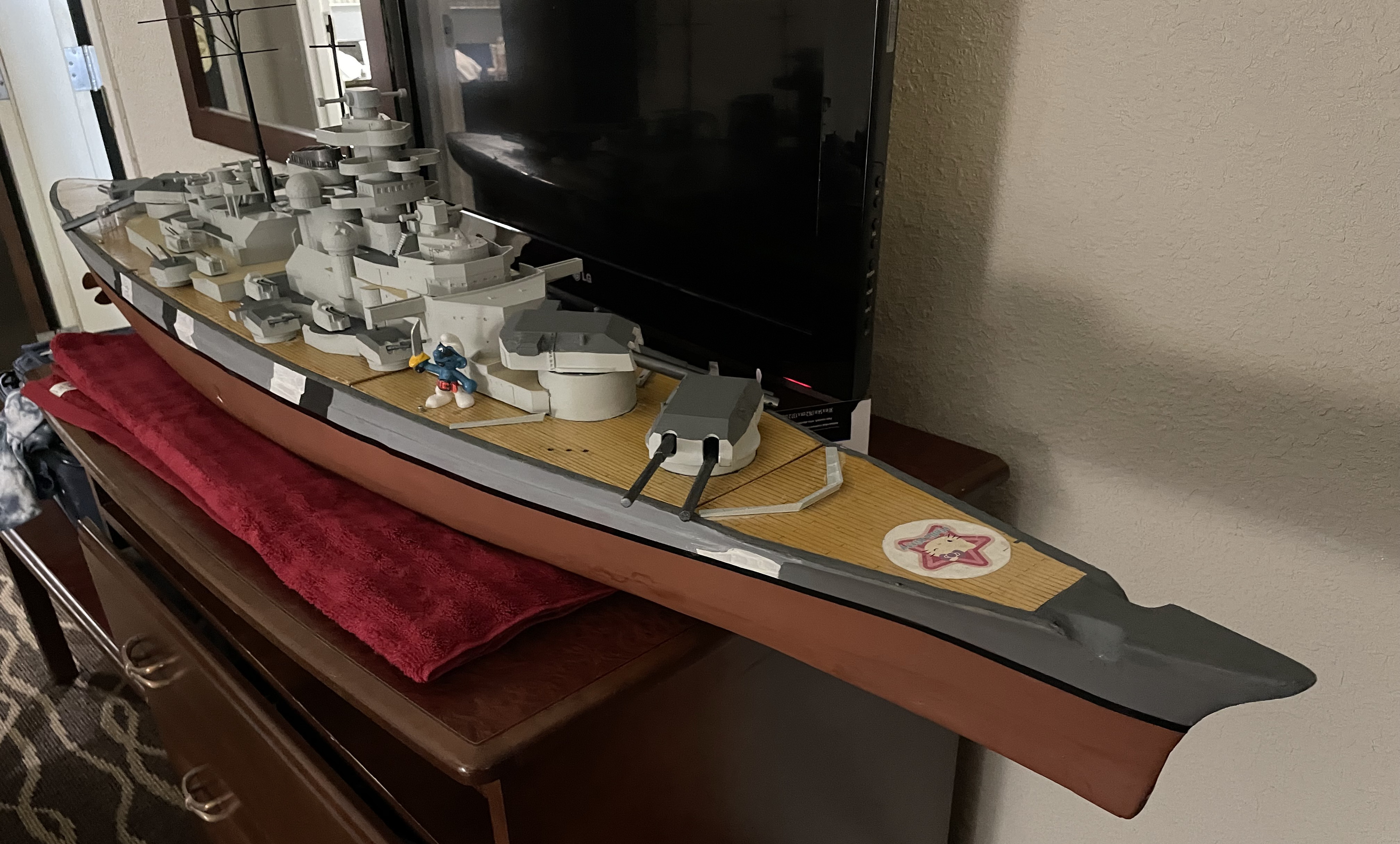 In the Hotel Room
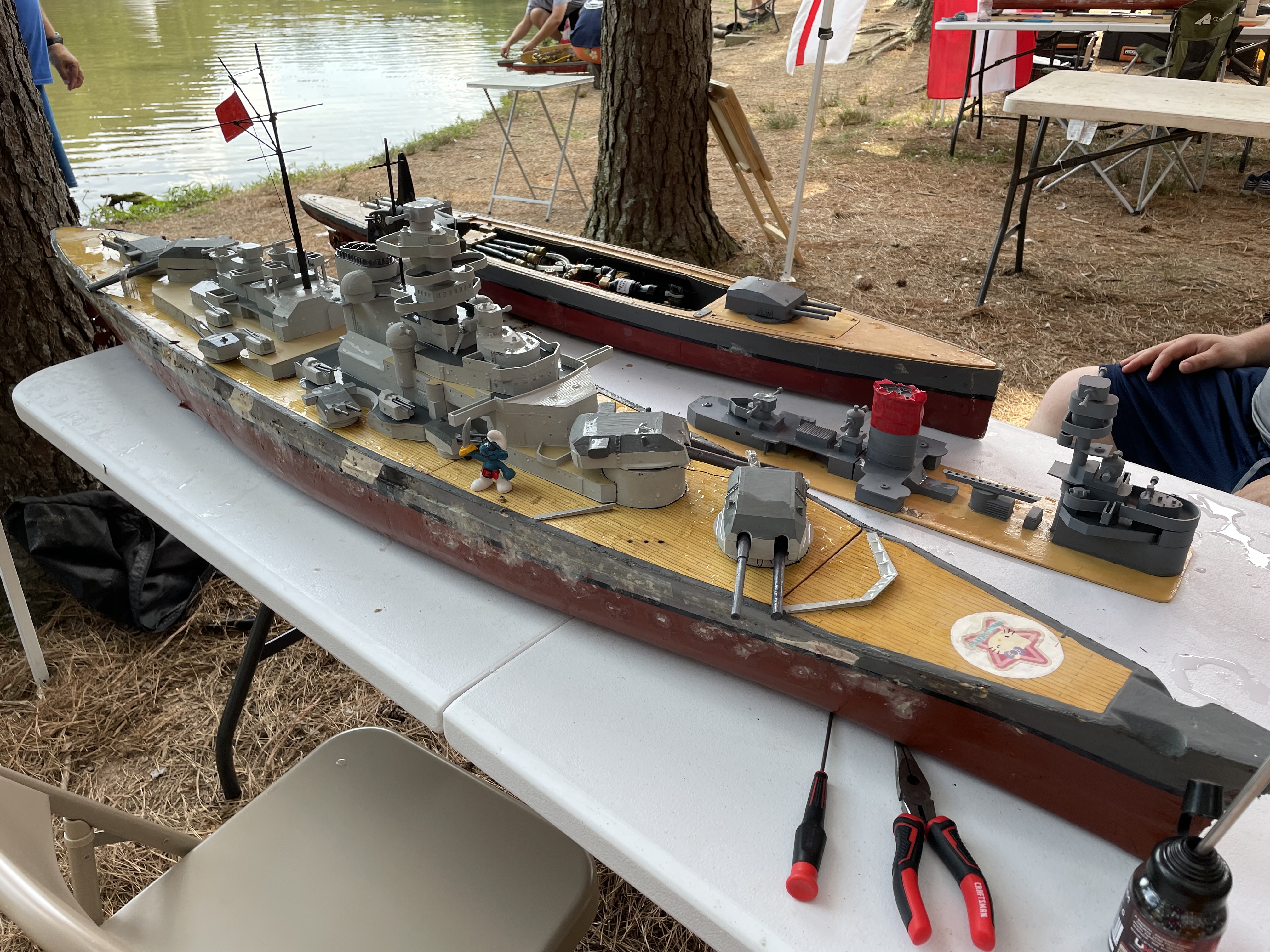 Lakeside
Finally, to close off the page, I have a couple of "cheesecake" shots showing the Bismarck, first in the hotel room, and last, at lakeside, with Smurf accompaniment. What a beautiful ship, eh??? I think Pirate Smurf agrees!
And before I forget, obligatory SABATON
That's all for now, folks - hope you've enjoyed the tour!