|
Article
Building the Goodson (H-Bridge) Throttle
by
Brian Eliassen
 | 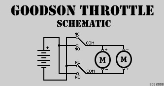 | PHOTO #1 : The Goodson Throttle schematic.
As stated, it's a very simple circuit. |
Overview
Back in 1996, I was fortunate enough to hear a conversation at our National Championship event where this circuit was discussed among the assembled captains. During this conversation, it was revealed that Lief Goodson, a battler from Florida, was the first person to use this circuit at a National event. This is a simple H-Bridge circuit and while others have tried to claim that it is their design or that they used it first, it was, in fact, used by Lief Goodson two years before anyone else. As such, it is named in his honor. Photo #1 shows the schematic of the very simple circuit known as the Goodson Throttle circuit. The circuit is based on two SPDT (Single Pole, Double Throw) switches. This type of circuit is quite old in that it has been used for simple, single speed, forward and reverse motor control since SPDT switches were invented. As previously mentioned, the official name for this type of circuit is the H-Bridge. The Goodson Throttle gives you full forward, stop and full reverse power. It is not intended to be proportional in any way. The circuit is very simple as well as reliable and this accounts for it being the most popular design within the hobby of model warship combat today for those that eschew ESCs (electronic speed controls).
Before you start building the circuit, you will need a few items. Also, I recommend reading the entire article at least once before starting. That way you will be completely prepared for what lies ahead and you'll have a better grasp of what is necessary to complete this with a working throttle. An incorrect installation could mean a fire, melted wires and/or exploding batteries. A direct short across the battery is not a good thing. I've seen all of these results from an inproper installation and it isn't pretty which is why I'm writing this article.
Parts and Tools List
- Two (2) 15amp lever or roller action SPDT switches (good quality). I use Omron V-15G6-1C26-K snap-action (Digi-Key part # SW151-ND)
- Silicone insulated 14 gauge multistranded wire. The silicone insulated wire works the best as it's more flexible. You can get this at Acer Racing. While you can use 12 gauge wire and it will handle just about any amperage load you can throw at it in this hobby, soldering the 12 gauge wire, especially when coupled with the Anderson Powerpole connectors, requires a proficient level in soldering skills. That's why I really recommend the 14 gauge silicone wire. In fact, I use 14 gauge wire in all of my ships.
- Wire cutters
- Wire strippers
- Soldering iron & solder
- CA glue and 5-minute epoxy
- Round servo wheel
- 2"x1"x1/16" aircraft plywood
- Small wood screws (4-8)
- 220 grit sandpaper (optional)
- About two hours of your time
| 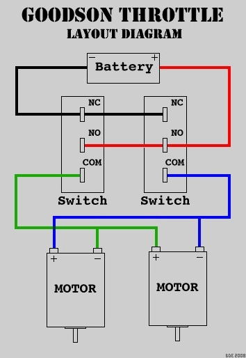 | | PHOTO #2 : Typical two motor layout for the Goodson Throttle. |
How The Circuit Works
In both the schematic and the layout diagram, this circuit shows a two-motor drive system set up so the motors counter-rotate. If you wish to add additional motors or remove one, the circuit basically remains unchanged. When everything is at rest and the two switches are not pressed, the negative side of the battery is being applied to both sides of the motor. In the R/C car arena, this is called "braking" as the motor(s) are more resistant to rotation. Once the servo presses one of the switches, it applies a positive voltage to that side of the motor(s) and the motor(s) start to rotate. The same applies in the opposite direction except that the motor(s) rotate in the opposite direction. This is how we get forward and reverse control. Note: Pressing both switches at the same time does not cause a short as you're just applying the positive side of the battery to both motor leads so the motors will not rotate as they are "braking" again.
Where's the Servo?
Photo #2 shows the complete layout for the circuit with two motors. The servo sits between the two SPDT switches and activates the switch levers with a cam attached to a servo wheel. Photo #3 shows an example of a cam used for motor control. Note that the cam is a semi-circle. If it were a simple two-sided servo arm, servo overthrow could cause a two-sided servo arm to move past the end of the lever. Returning the arm to it's center position could then jam the arm under the lever at which time (and after the colorful metaphors) you have to remove the lid on your radio box to fix it. I know, it happened to me on my first ship. Hey, that's how you learn. So use a semi-circle cam for your throttle. It'll make life easier.
Assembly
1) The first thing to do is to put the servo into position between the servo rails in the radio box. Place two pieces of 1/4" square hardwood strips on either side of the servo. This is what you'll be attaching your SPDT switches to as connecting them to the servo directly can cause you a great amount of grief if you ever need to remove the servo for any reason. Doing the installation this way lowers the amount of time to swap out a servo at lake-side and that's a good thing. If you're using small SPDT switches, you'll probably want to mount the square hardwood pieces to the top of your servo rails as mounting them flush would put the lever too low for the servo cam assembly. Once you have them in the correct position and the switches will attach and still allow the servo to be installed between them, you need to waterproof them.
2) Once you've waterproofed the switch mounting rails, it's time to solder the wires to the switches. I recommend doing this outside of the radio box as it'll give you more room to work. A trick I use is to put the switches in a vise oriented in the same direction and placing them about 3-4 inches apart. This will leave you plenty of slack to fit around the servo when you install them. Also remember to leave enough wire to exit the radio box and route to both the battery and the motor area. A few tips are:
- Solder the wire to the top of the contacts. Remember that a servo needs to fit between the switches so any wiring across the connectors may put the wire directly in the way of the servo.
- Use connectors on the leads after they leave the radio box. This will help in the future when you need to remove the radio box. I always use Anderson Powerpole connectors for this.
- At the end of the wire, remove twice as much of the insulation as needed. About 3-4 inches back from the end of the wire, cut just the insulation and slide the insulation towards the exposed wire. If you do this correctly, you'll have a section of exposed metal wire in the middle of the wire and some at the end.
- "Tin" all your parts to be soldered. What this means is that any exposed metal which will be soldered should have a coat of solder on it before the final soldering. Quantity isn't important...getting the metal hot enough to actually have the solder bond to the surface is MUCH more important. But be careful not to put so much heat on a part that you melt it. Moderation is the key.
- Always wire positive battery voltages with red wire and negative battery voltages with black wire. Wires that will, at different times, carry both positive and negative voltages such as the common wires from the switches to the motors in this circuit should be another color such as blue, green or yellow. Keep this system throughout your ship and you'll have less meltdowns.
- It's not overly important whether positive or negative is on NO or NC. Just so long as you don't mix them up and have one positive going to NC and the other going to NO on the other switch. This is a direct short. Get the fire extinguisher! Also, the common leads should ALWAYS go to the motors. Hooking them up directly to positive or negative will cause a direct short. Get the fire extinguisher, again!
| 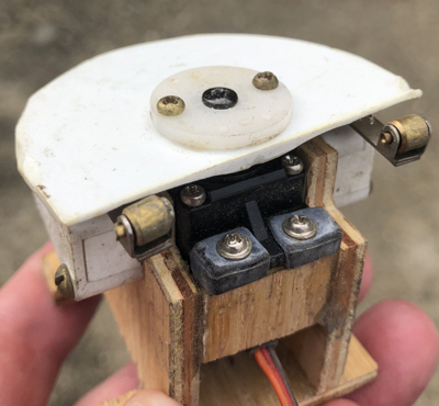 | | PHOTO #3 : Cam position compared to location of the lever rollers. |
3) Once you've soldered the switches properly and checked them over carefully for a proper hookup, you're ready to install them. Note where the center-line of the servo splined drive shaft is on the two switch rails and remove the servo. This will show you where the servo cam will sit. I always try to put the lever roller just a little past the center-line of the servo splined drive shaft. This will have the servo cam covering most of the lever except for the roller end. Use a good 5 minute epoxy to attach the switches and use a clamp to hold them. Getting them into the correct position is very important before they dry. You want a cam, when rotating, to push down the lever but not too much. You want to make sure the switches are low enough not to stall the servo but high enough so the cam will hit the roller level as you can see in Photo #3.
4) Make sure the wires between the switches are out of the way and install the servo. Plug it into the receiver and turn on the radio to "center" the servo before proceeding.
5) Install the servo wheel with the cam.
Copyright © 2002 Brian Eliassen
|