|
Article
Add Buttons To An Airtronics VG600 Transmitter
by
Brian Eliassen
WARNING: This modification requires that you open and heavily modify your radio. This will void any warranty. The author of this article is not responsible for any damage you may cause to your radio or to yourself. If you feel you are incapable of modifying a transmitter yourself, please seek out professional assistance.
UPDATE: This modification was originally intended for use with servos and switches. Since the creation of this article, Team Delta released control boards which emulate the function of a servo/switch combination, in effect, providing a solidstate switch in one easy package. The instructions have been modified to show where a modification is necessary if you are using Team Delta boards to fire your cannons. I would like to thank Patrick Clarke for providing the necessary information for modifications to the circuits to allow the Team Delta boards to fire. The original design with the eight (8) 2.2K resistors did not provide full deflection of a servo as it was unnecessary in this function and provided for quicker firing. The Team Delta boards need full deflection to operate so the additional notes for Team Delta board use is noted below throughout the article when applicable.
Equipment:Before you start on this modification, you will need a few items. Some of these aren't too critical but if you have all of them, it'll pretty such guarantee an easy modification experience. Also, please read the entire article at least once before starting. That way you will be completely prepared for what lies ahead.
Note: Some photos can be clicked on for a more detailed picture.
Parts and Tools List:
- Four (4) normally open panel mount momentary switches (good quality). I use C&K 8121SHZGE snap-action pushbutton (Digi-Key part # CKN4011-ND)
- Four (4) pushbutton tops. This is a luxury item. You don't really need them but it is easier on your thumb. I use C&K 752701000 (Digi-Key part # CKN1103-ND)
- SERVO/SWITCH: Eight (8) 2.2K 1/8 watt resistors OR
- TEAM DELTA: Four (4) 1.0K 1/8 watt resistors and four (4) 3.3K 1/8 watt resistors
- Four (4) inches of 20 gauge multistrand wire (22 or 24 gauge will work fine as well)
- Small wire cutters
- A small sheet of 1/8" aircraft plywood
- A small saw
- A bottle of black paint and a brush or a can of black spray paint
- Drill with 3/32" and 1/4" drill bits
- Soldering iron & solder
- Philips screw drivers (#1 & #2)
- Pencil and ruler
- About three (3) hours to do this
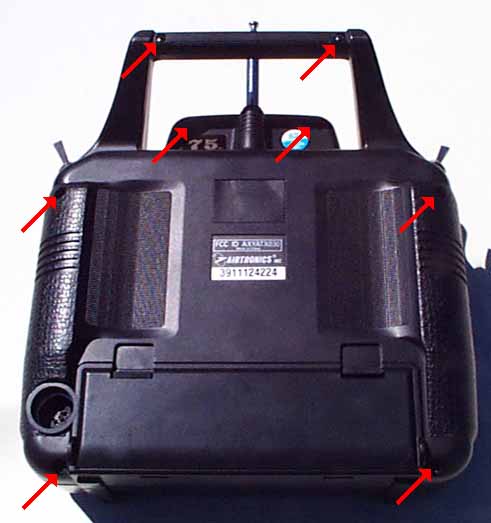
 | 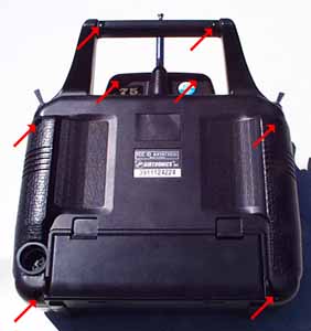 | | PHOTO #1 : The red arrows point to the screws. |
1. Remove the battery. Open the access door on the back of the radio, unplug and then remove the battery.
2. Remove the antenna. Do this by twisting it counter-clockwise and then pull it out. This is necessary as the new VG600 has a bracket wrapping around the rear case. If you don't remove the antenna, you can't remove the case.
3. Remove the screws. There are eight (8) screws on the back of the transmitter. These screws are different sizes and you have to look for them. Don't miss the two small ones in the handle. Photo #1 shows the back of the transmitter. The red arrows show where a screw needs to be removed.
4. After getting all the screws out, fold the back over to the left. You can push out the battery plug and fold the back cover over with the buddy-box plug still connected. Do not disconnect the buddy box connector!
5. You will note two gimbal assemblies inside the transmitter. We want to remove the one on the left side. This is actually the right gimbal (when held normally). You will see two (2) groups of three (3) wires (six (6) wires total) goinging into two round objects. These are the potentiometers that the transmitter reads to know there the stick is located. Cut these small wires about 1/2" from the potentiometers. This will leave plenty of wire for this modification. Do not throw the gimbal away as you may need it for parts.
| 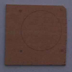 | | PHOTO #2 : The switch plate with pencil markings. |
6. After cutting the six (6) wires, put the back cover of the transmitter back on (without screws) and turn it over. You will note four screws around the right gimbal assembly. Remove these screws. We will use these screws later to mount our switch plate so don't lose them. Take the back of the transmitter off and remove the gimbal assembly. It should just slide right out. If it doesn't make sure you removed all four (4) screws and disconnected the six (6) wires which were going to the gimbal's potentiometers. Your transmitter should look like this when you're done with this step.
7. Now we need to make a new plate to cover up the hole where the gimbal used to sit. Using a small saw, cut a 23/4" x 23/4" piece of 1/8" aircraft plywood. I used some scrap wood I had laying around the garage. This size piece will be large enough to cover both the large hole where the stick used to be as well as the trim tabs. Note: This piece of wood will not sit flush over the trim tab holes but this will not matter. If you wish, you can glue small pieces of wood over the trim tab holes or just leave them open. I left mine open and I've never had a problem with debris or water entering the transmitter through the holes.
8. Place the plywood over the open gimbal hole. It will not be centered but the extra length will obscure the trim tab holes. While holding the piece of plywood in position, tilt the transmitter on its side and using a pencil from the front, mark the main opening as well as the four gimbal mounting holes onto the plywood. This is pretty important procedure as the position of the firing buttons relies on the accuracy put into this step. What you end up with should look like Photo #2.
| 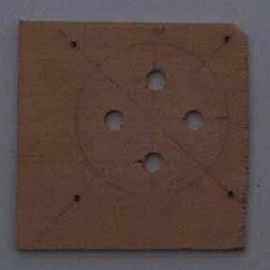 | PHOTO #3 : The switch plate with
all the holes, ready to be painted |
9. Using your ruler as a straightedge, draw two straight lines across the large circle from the smaller circles. This will create a large "X" on the switch plate. Where the lines cross is the center of the hole. Using your ruler, mark from the center where you would like to put your switches. Be sure to leave at least 1/2" between them so you aren't always firing extra cannons by mistake due to "fat fingers".
10. Using your drill and a 3/32" drill bit, drill out the screw mounting holes on the outside of the large circle.
11. If you purchased the recommended switches mentioned in the parts list, you will need to use a 1/4" drill bit to drill out the holes for your switches inside the large circle. If you bought different switches, use whatever drill bit size will allow you to mount your switches on the switch plate. Note: It's always better to go too small than too large with your drill bits. You can always drill out with a larger bit if the switches don't fit. It's a bit harder to add wood to make them tighter if you do it the other way around. If you do make the holes too large, just cut out another switch plate and continue. When you're done, at this point, your switch plate should look like Photo #3.
| 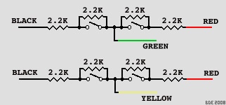 | PHOTO #4 : The two circuits in
schematic form for servo operation. |
12. Time to paint! Grab some black paint and a brush or your spray can and paint the front side of the plate. This is the side with the pencil markings on it. Paint the entire thing. An hour later, it should be dry. Once mounted, the black surface really looks great. Of course, you can go nuts and paint just about anything you want to on it. I've always wanted to do a bullseye in red and white.
13. After the paint has dried, mount your switches and then attach the plate to the transmitter by attaching it with the four gimbal mounting screws. The screws used to mount the gimbals are perfect for this as they are a more agressive thread than a machine screw. This is due to their use in attaching a block of plastic to the front of the transmitter. As you can see from Photo #6, these screws work well.
| 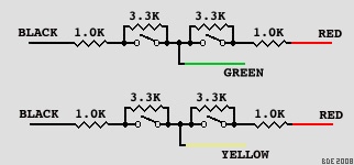 | PHOTO #5 : The two circuits in schematic
form for Team Delta operation. |
14. Now the fun begins. Pull out the soldering iron and the solder as we are going to be building the two circuits shown above. If you're going to be using servos and switches, use the circuits in Photo #4. If you plan to use Team Delta control boards, use the circuits in Photo #5. Soldering really isn't that difficult. The first secret to soldering is planning. If you plan how you want your circuit to look before you start, it should turn out pretty nice. The second secret is tinning. This is applying solder to the parts BEFORE you solder them together. Once I tin, I never use additional solder as the tinning is actually enough to get a good solder joint. I learned this in soldering school. Soldering school consided of a 40 hour class covering all the nuances of solder and electro-static discharge. I took the class twice as the certification was only good for two years and I was a "solder monkey" for three years at NASA. Assemble the circuit being careful not to leave any debris in the radio. If you're more comfortable doing the soldering before you mount the plate, you can do most of it outside of the radio until you need to connect the colored wires.
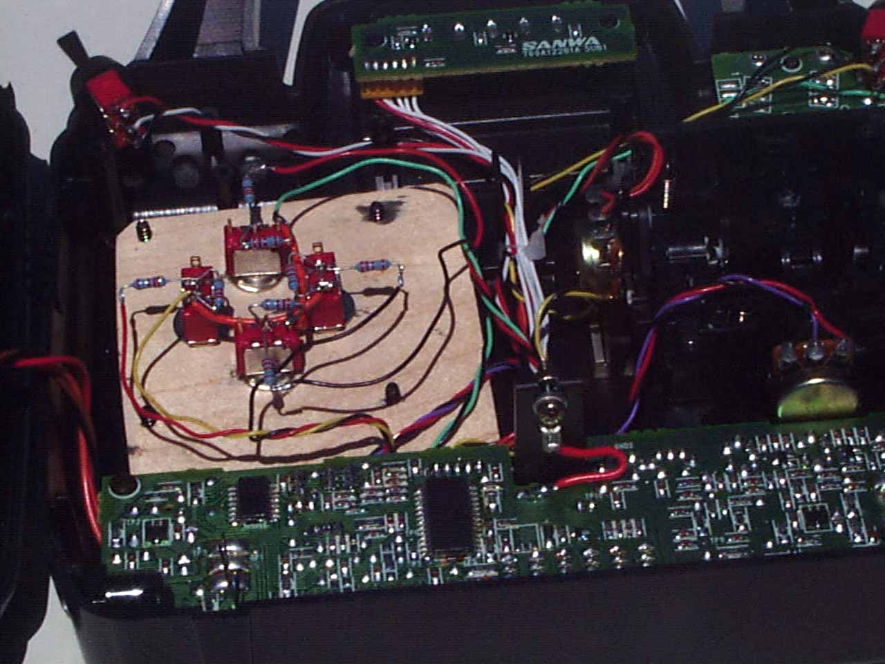
| 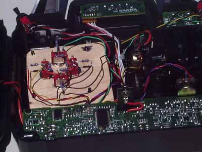 | | PHOTO #6 : The circuits have been installed and are ready for testing. |
15. Testing time but first we need to get the radio back to a condition where this will be easy. Place the back cover back on the front section being sure the battery connector is inserted into its slot. Reattach the antenna by screwing it in. Install the battery and put the cover on. At this point, everything should stay together as the antenna will hold the back case on. Turn it over and turn on the radio. If you don't see any smoke or smell burning electronics, you're half way there. Turn on your receiver and test the buttons. You should have movement in both directions on the two channels we've modified. If you're planning on using Team Delta boards, test initially on servos and then test with the Team Delta boards. This will help you isolate any problems you may have. If a servo test is working but the Team Delta board is not working, you've elimiated one variable from the list of causes. If you are unable to get any movement out of a servo, go back to the beginning of this article and start over while looking for the problem. If you get more movement one way than another, make sure you do not have Dual Rate or Adjustable End-Point modifications active on your radio.
16. If you bought the recommended switches and pushbutton caps, install these now. From time to time, I've had to enlarge the hole in the caps with a small drill bit. If you need to do this, be careful as you can easily push the spinning drill through the cap. This will render the cap useless.
17. Turn over the radio and put all eight (8) of the screws back in place being careful to put the proper screws in the proper holes. The handle holes use the smallest screws. The "antenna" holes use the short large screws.
18. Congratulations, you're done. Now you can show your friends how capable you are with a soldering iron and cause massive carnage on the water.
Copyright © 2008 Brian Eliassen
|